Remark

This blog started with an old safe I bought with unknown content and combination. It describes the process of opening, finding the origins, contents and mechanics of the safe.

The posts are closely relate to each other and should probably be read in chronological order. Therefore, if you are visiting this blog for the first time you might want to start reading with the oldest entry and work your way back to the present time.
Showing posts with label Combination lock. Show all posts

Sunday, December 12, 2010

Picked the key lock

I managed to pick the key lock of the safe using these lock picks. Now it only takes me up to 20 seconds to pick that lock. It seems to be a standard cylinder lock with now extra security. The cylinder rotates a few degrees and then stops. When I now turn the combination dial I can feel the key cylinder changing its rotation angle and the dial rotation is hindered by some friction.

A first analysis of the dial indicates a deep depression between 55 and 59. At the moment I assume this to be the cam gate location. Once the notch drops into this I have to turn the key cylinder slightly back to get out of it.This indicates that the cam gate has steep sides and maybe even the lever nose. If that is true I wont be able to measure the lever nose depth by measuring the cam gate width. Another approach would be to measure the key cylinder rotation angle which should be proportional to the nose depth in the cam gate.

From an expert on the internet I learned that this type of safe typically has fixed flies and the cylinder key lock is essentially the handle.

The fixed flies are much cheaper to manufacture. It essentially means that the safe has two different combinations depending on the initial dialling direction. This slightly complicates the standard approach since direction has to be taken into account. I might need to measure the fly width to get a better understanding of the lock.

The key lock being essentially the handle means that to open the safe one would first dial the correct combination and then turn the key to retract the bolts.

The next step is to set up some good way to measure the cylinder rotation and the graph the nose depth (angle) at the cam gate for different combinations.

More soon...


Sunday, August 30, 2009

The Locking Mechanism

When reading my blog I noted that it really should be read chronologically since the individual entries relate strongly to each other on the same project. Maybe a blog is the wrong format for this project. Anyway, back to the safe.

I had a close look at the locking mechanism. First I removed the inside cover of the safe door by taking eight screws out. The back cover has been bent open once before to unlock the safe from within through a hole in the bottom of the safe. The paint has chipped of along this bent line and this is clearly visible.


This is the sign on the inside cover of the door.


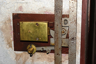
Taking off the cover exposes the mechanics of the locking mechanism. The door is filled with some type of concrete for fire protection. A metal plate fixed to the concrete is holding the locking mechanism. In this picture the locking bolts are pushed out, the safe would be locked if the door was closed.


There is a grey steel cover over the main part of the combination lock with a small soft piece of metal holding an extra lock up (underneath the grey cover), which would engage if the small metal piece (called trigger) was broken. This is called a relocking device which is mentioned on this sign on the front of the safe:

The idea is that somebody forcing entry will trigger this by either breaking the little metal piece or melting it. The safe would then permanently lock itself and make it impossible to be opened without major mechanical force or very detailed knowledge about the relocking device. Note that in my safe the relocking device has been tampered with and is not installed properly any more. Simply standing the safe upside down would disengage the relocking device. Normally there should be a spring loaded pin in the pivot of the relock arm, that "dead-locks" the lever in place.

I assume that in a previous forceful entry this relocking device was triggered and had to be broken.


In above photo I removed the grey steel cover exposing the brass case that is holding the combination locking device. Next I removed the brass cover:


The brass cover is holding the wheel pack (see photo below). The pin on the top right of the cover presses on a release spring in the brass casing. Only if the brass cover is on the casing the lock automatically disengages when the nose enters the gate. The pin can easily be simulated by pressing the spring with a screw driver. I guess this is another device to make forceful entry into the lock difficult.


The combination lock is a Herring Hall Marvin manufactures lock. The wheel pack consist of three wheels called "hole change" type. Each wheel has holes in increments of 4. The top most wheel and the bottom wheel have even numbers while the one in between has odd numbers. A combination is set by carefully disassembling the wheel pack and putting the grey metal pins in the holes with the desired numbers. The bottom wheel corresponds to the first number to be dialled in the combination and so on. All wheels are different and have to be reassembled in the same order as they were disassembled, otherwise the desired combination wont work. It is therefore very important to test the combination with the door open before locking the safe. Here are some photos of the disassembled wheel pack. Note that the wheels are numbered from 3 the top wheel to 1 the bottom wheel to indicated their corresponding position in the combination.


With this type of lock the starting direction when dialling in the combination is important since the wheels don't have what is called movable flys. The gate and nose configuration is such that the lock will disengage entering from either way. This means that there are two slightly different combinations that will open the safe depending on the starting direction.

Judging by the size of the gates in the wheel pack and the fence (cylindrical in this case) I would guess that there is a tolerance of about 2 to 3 numbers. This means that one could be out by one with each number when dialling the set combination and still open the safe. This safe is in the first instance a fire protection safe and is not regarded as having a high security locking mechanism which explains this tolerance.

Now the interesting thing in my lock is that the numbers selected on the wheels do not correspond to the numbers that open the safe. This most likely indicates that the wheels in the wheel pack have been taken from a different type of lock. Since I have a working combination I know which number in my combination relates to what number in the wheel pack. I can therefore make a lookup table of corresponding numbers for this wheel pack. With this lookup table I can set my own combination. I will try this soon and report back.

Wednesday, July 29, 2009

How I opened the safe

The first thing I tried was to follow the instructions given in "Safecracking for the computer scientist". If you are not an expert, you will have to read some parts of it if you want to understand the following in detail.

Essentially there should only one place where you feel a change in resistance when turning the dial, it is called the gate. The gate will be found at the same location each revolution. For this make and model of the combination lock (Sargent & Greenleaf, group 2, three wheel lock) it should be somewhere between the numbers 95 and 15. For a combination lock of this type and if it is in good condition it should be easy to found by feel (not so much sound). The lever nose drops into the gate each turn. If all the other wheels (three in this case) are aligned correctly the lever nose will drop into the gate all the way and enable the unlocking mechanism. The method of manipulating the combination lock (finding out the correct combination) relies on small imperfections of the wheels. Essentially one systematically dials in different combinations and measures how deep the lever nose dropped into the gate. This is done by finding the left and right contact points between the lever nose and the gate (they can be felt). The results are graphed and ideally one number of the combination can be read of that graph. Then a few experiments can indicate which place the number has in the sequence of the combination. The experiment is then repeated in the same fashion, only by presetting that found number while changing the others. If one is able to detect the locations of the left and right contact points accurately and repeatably one should be able to find the correct combination in less than an hour.

Well all that sounds reasonable straight forward, only that my dial was not turning easily and randomly sticking. I was able to find the gate and even get a reasonable idea where the left and right contact points were but a few experiments showed that my measurements were not reliably repeatable. It was just to difficult to turn the deal smoothly and feel the subtle change in resistance.

My next attempt was to apply some WD-40 to the combination lock and that improved things greatly. The dial was now turning smoothly and the change in resistance stood out very well. So I made some safe cracking graph paper and made a few runs of filling them in:


One has to look for where the left and right contact points are the closest to each other. I found some areas of interest and one place around numbers 70 to 75 were there was a big jump in the size (the nose lever is held higher above the gate), but I could not reproduce the areas of interest by closer investigation. Generally I found it difficult to determine the contact points to the required accuracy.

During my time of dialling in different combinations I noticed marks on the knob of the dial.


I had noticed them before, there were two sets of different marks (lines and round holes) with four marks for each of the sets. A safe expert on All Experts had already suggested to me to try these marked numbers. I discounted them since I was sure I only needed three numbers in my combination and it is very hard to tell to which exact number each mark belongs. I found however that the set of round marks had one mark on zero. I discounted the zero mark and rounded the remaining three marks to their closest multiple of 5 numbers. This gave me three numbers to work with for which there are nine different orders of dialling them in. I wrote all nine sequences down and started dialling them in systematically (see this entry on how to correctly dial in a combination). The lever nose clicked very audible into the gate after dialling in my third combination. I turned the handle and the safe opened revealing that is was stuffed full with things.

I will write more about the content and the safe soon. I want to have a look at the combination lock from the inside (see what happens between the numbers of 70 and 75) and maybe even set my own combination.

Sunday, July 19, 2009

Closer inspection of the safe

The safe is 50cm wide, 70cm high and 51cm deep. At the top left it says in golden letters:
Herring Hall Marvin Safe Co.
Hamilton Ohio


At the bottom of the door there is a sticker with the same information:


Underneath that there is a plaque that says:
Underwriters Laboratories, Inc
Inspected
Locking Device
Group 1 No 114275


On the top hinge is a serial number:
15542


The combination dial has 100 positions, the knob shows HHM (for the make).

Right from the dial are two drill holes. Drilling into the locking mechanism is a common way of opening a safe. The combination disks can be aligned visually or the opening triggered manually. For this reason some safes have cobalt plates embedded near the lock which is very difficult to drill and requires specialised equipment.

The right hole is only shallow. The left one is about 40mm deep but does not penetrate the locking mechanism. I don't think these holes were successfully used to open the safe.


In the base of the safe a section has been cut out. The outer hull has been cut away, the insulation (concrete) has been removed. Another metal layer beyond that has been cut out and bend to the side. Behind that there is a sheet of metal, which in my opinion, has been put there from the inside to close the hole.


I think somebody got into the safe this way and probably managed to unlock the safe through this hole from the inside. This means if there were any drawers or compartments in there, these would have been damaged in the process. Of course I don't know when that happened, but I don't think I will find great treasures (maybe a business card from a locksmith).
This is the safes weakest point at the moment. The metal sheet could easily be cut away.